Fabrication of a Michelson Interferometry…
Design and fabrication of a Michelson Interferometry based vibration sensor
Shashi Kumari, A. Narayan and R.P. Sinha
Department of Physics, Patna University
Small amplitude vibrations are difficult to measure. Light interferometric methods have a good sensitivity which is of the order of wavelength of light used. This method, in effect, causes very small disturbances in objects under observation. We have fabricated a system that uses Michelson interferometer in which overlapping of two coherent waves produces interference. A Helium-Neon Laser source of 5 mW power is used as the light source. A beam splitter is used to split the light beam into two coherent beams. One beam goes to a fixed mirror and the other goes to a vibrating mirror from which the beam is reflected. These beams are made to recombine. The resultant interference pattern is detected with the help of an indigenously fabricated LDR-based photo-detector assembly for electronically detecting fringe passage. The signals have been displayed with an oscilloscope. In order to produce vibration, one of the mirrors of the interferometer has been fixed to the cone of a speaker. A low frequency oscillation in this mirror produces moving optical fringes which after conversion into electrical signal are displayed by the oscilloscope. Snapshots of the resulting fringes were recorded with a digital camera for further analysis. This system has the sensitivity to detect oscillations of amplitude as small as 3.8 X 10⁻⁴ cm. We have tested this apparatus for low frequency sinusoidal vibrations.
Keywords: Vibration sensor, Michelson Interferometry.
l. Introduction: It is difficult to measure vibrations of very small amplitude. Techniques based on Interference of light have a good sensitivity which is of the order of wavelength of light used. Interferometric methods have another advantage in that they cause very small disturbances in objects under observation. Lasers were developed in the early 1960’s. Since then, people have attempted to measure vibrations with help of Lasers. Lasers are highly monochromatic and directional. This makes them suitable for interferometric measurements1-5. An interferometer mixes the scattered light with a reference beam resulting in an optical signal having a spacial and temporal intensity distribution that carries information about the moving or vibrating system. By using this procedure the displacement of the object can be precisely measured as a function of time. Several variants of Laser based distance and vibration measuring technique have been developed for different applications such as structural dynamic testing, acoustic quality control and medical diagnosis6,7. We have tried out a simple technique for study of low -frequency vibrations using this Laser Interferometric technique.
This work presents a very simple laser-based vibrometer that we have fabricated in our laboratory. It is suitable for characterizing vibration transducers such as piezoelectric transducers and dynamic loudspeakers. As the cone of a dynamic speaker is quite light, optical techniques are preferable over other techniques to measure parameters such as acceleration. We have given a general introduction of vibrations analysis of a speaker system.
In a dynamic speaker system a light coil is fixed on a moving cone. This coil is placed in a strong magnetic field. The theoretical expression related to electrical and mechanical quantities of vibrating coil in the magnetic field are derived below.in section II. In part III the data analysis were presented with experimental set up . Observation and calculation is given in part IV, while result and discussion were explained in the part V.
II Theory: A loudspeaker is a device which converts electrical energy into sound8. It has a moving cone firmly connected to a coil at its center. The coil is placed in the strong radial magnetic field of a permanent magnet. The field lines are in radial direction and lie in a plane perpendicular to the x-axis as shown in Fig. 1. Alternating current flows through the coil and causes the speaker cone to vibrate, thus producing sound waves to the air.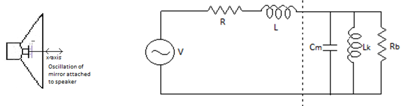
Figure 1 Fig. 2. Equivalent all-electrical network to a loudspeaker.
Consider a loudspeaker in which the coil is fed with a steady sinusoidal voltage V0 of amplitude and angular frequency ω. The amplitude of the alternating electric current i flowing through the coil is i0 . The force F on the coil can be written as F=Bli, with B the magnetic field strength at the coil, and l the length of wire in the coil. The resulting motion is in the direction of the x axis. Since the coil moves perpendicularly to the magnetic field, and the wire is perpendicular to the field and to the motion, there is an induced electromotive force given by E=Blu, where u is the coil speed8,9
If the amplitude of vibration of the loudspeaker is small, then it can be considered as a linear system.9 In such case all oscillatory quantities can be expressed as sinusoidal functions having angular frequency ω . Let us call x the position of the center of the speaker cone along the x axis, and define the equilibrium position as x = 0 (The position in the absence of any external applied voltage). The amplitude of the displacement is x0 . It is then possible to characterize the speaker system by fitting the experimental data of the current normalized amplitude of vibration, x0/i0 and the impedance, Z0 = V0 /i0, as functions of ω using the corresponding theoretical expressions. Using carat (^) for representing phasors corresponding to the oscillation parameters, we can write

where the time derivative d\widehat{x}⁄dt was replaced by jω\widehat{x}8 (For sinusoidal steady state functions \widehat{x},d\widehat{x}⁄dt=jω\widehat{x}). As the product Bl is real, the j in Equation (2) means that ̂\widehat{E} and ̂u lead the displacement \widehat{x} ̂in phase by 90°.
Let R and L respectively be the electrical resistance and the inductance of the coil. Let the mass of the coil and the speaker cone together be m, the elastic constant of the suspension k, and the dissipation constant b. We assume that the speaker cone and the coil move together as a ‘‘rigid piston,’’ which is a good approximation at low frequencies, for which the sound wavelength is long compared to the diameter of the speaker cone8,10,11. The voltage V that is applied to the speaker coil must overcome the induced electromotive force, and the voltage across the resistor and the inductor. So
\widehat{V} = \widehat{E} + R\omega\widehat{i} + jwL\widehat{i}
(3)
where the voltage across the inductor ( Ldi/dt ) has been written as jωL\widehat{i}.The force on the mass m can be expressed as \widehat{F} - k\widehat{x} - jωb\widehat{x} = -mω^2\widehat{x} . (4)
where - k\hat{x}is the elastic force, -bu=-b dx⁄dt→-jωb\hat{x} ̂is the frictional force plus the air resistance force and md^2x⁄dt^2 → -mω^2\hat{x},is the mass times acceleration. Note that the problem expressed by Eqn.(4) represents a damped oscillator subjected to an external force \hat{F}, with b the damping constant (which depends on the characteristics of both the speaker and the surrounding air). If we eliminate \hat{F} in Eqns. (1) and (4) and calculate \hat{x}/\hat{t}, we obtain
\frac{x_{0}}{i_{0}} = |\frac{\hat{x}}{\hat{i}} |= \frac{Bl⁄k}{([1-ω^{2}m/k]^{2} + ω^{2}b^{2}/k^{2} )^{1/2}} (5)
with the parameters a1=Bl⁄k, a2=m⁄k, and a3=b⁄k
An important conclusion that may be
drawn from Eq.(5) is the existence of a resonance at ω=[(k⁄m)-(b^2⁄
2m^{2})]^{1⁄2}. In practice, the
damping constant is generally small (b << \sqrt{k}{m}[/latex]), so
the resonance occurs at [latex]ω ≈ \sqrt{k}{m}[/latex] Also,
as we might expect, a strong magnetic field B, a long length of the wire in the coil l, and a small elastic coefficient k, result in greater motion, and the term Bl⁄k appears
naturally in the numerator of Eq. (5).
Experimental : The Michelson interferometer has two mutually perpendicular limbs at the end of which there are mirrors. The instrument basically measures optical path difference between reflected beams from the mirrors attached to the two limbs12. In the present set up, one limb had a fixed mirror and other contained a mirror mounted on a speaker cone. The mirror attached to the speaker cone represented a vibrating reflecting surface whose vibrations we are interested in studying. The second mirror vibrates when AC signal is given to the speaker coil. The interferometer set up was arranged as shown in Fig. (1),We used a 5 mW optical output He-Ne laser (632.8nm) as light source. The beam from the Laser was made incident on a beam splitter using which two coherent beams were obtained. One beam was sent to a fixed mirror and was reflected back from it and the other beam was transmitted through the beam splitter to the vibrating mirror and was reflected from it. The two reflected beams recombined at the beam-splitter and interference fringes were obtained.
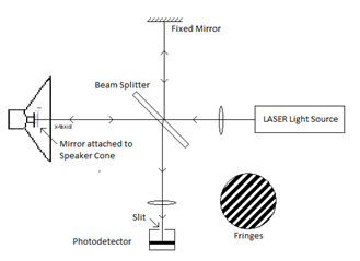
recombined at the beam-splitter and interference fringes were obtained.
A movement of one mirror by λ⁄2 distance causes one full fringe shift at the location of the optical detector. A thin slit was placed in front of the photo detector and aligned parallel to the fringes to obtained maximum intensity variation with the shift of fringes. A LDR (light dependent resister) based photo-detector was used12. The electronic circuit for further processing is described below.
A 50 Hz sine wave signal was given to the speaker from a function generator. This causes the speaker cone to vibrate at 50 Hz frequency. The function generator output was monitored on the channel 1 of the CRO. The circuit at the LDR and sensor side is shown in the diagram. A 12 volt dc source was connected to the LDR and the current through it was measure using a 741 op-amp based inverting
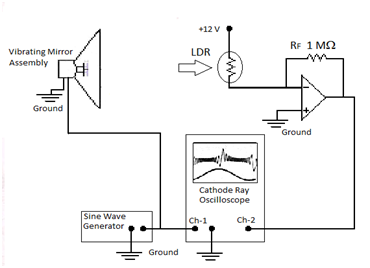
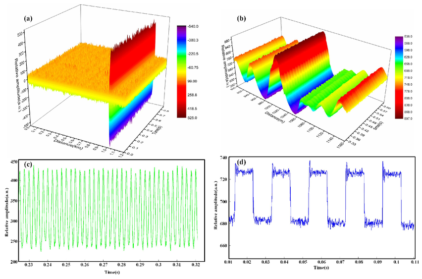
amplifier circuit. The voltage obtained at pin 6 of the op-amp was monitored on channel 2 of the CRO. The CRO was adjusted with ac coupling and the sensitivity was adjusted so that the fringe shift during vibration was clearly observed as a voltage pattern12 . The LDRresistance can be easily obtained from voltage pattern observed on CRO (Fig. 5). A dual trace 30 MHz Systronics make CRO was used, and the wave form on the screen which represented crossing of light and dark fringes across the detector slit was photographed using Kodak digital camera and data was obtained from it was analyzed manually.
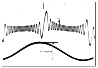
III(A). Data analysis : I have determined two parameter for vibrations of different amplitude .first the scale (x-axis represents time) was determined . The peak through separation of ch-1 signal (λ /2)is 10m sec. If (say) this covers a length of 11cm then x-axis is (10/11) m sec/cm.
Principle of displacement measurement:
Suppose that the peak to peak displacement of mirror O2 = Δ d and the total number of fringes shifted during this process = n. When mirror covers a distance of λ/2, it causes a fringe shift of 1 fringe. So the peak to peak displacement Δd= nλ /2, where λ = 632.8nm (He-Ne laser)
IV Calculation and observation:
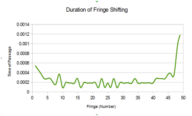
A large number of snapshots of the CRO screen were taken. As an example, the individual fringe shift measurements for snapshot #100 are shown below.
| X=22cm | Nt=25 |
| T =0.02s | Displacement per fringe = λ/ 2 (cm) Total Displacement in P-P movement =7.93E-04 cm |
V. Conclusion: The main aim of this work was development of instrument hardware so that small amplitude vibrations can be measured. We demonstrated through our work that this is possible. We have shown that interferometric techniques can be used for measurement of very small amplitude vibration of bodies. In the present experiment we attached small mirror to a vibrating body (speaker cone) and obtained interference fringes with its help.
We measured fringe shift as a function of time that gave us the amplitudes of vibrations of the speaker cone. This technique is useful for other bodies too. We can measure any vibration sticking a mirror on the surface of the vibrating body and measuring shift of michelson fringe.
Some of the systems that can be studied by this method are,vibration of musical instrument,vibration under different situation such as drilling, hammring and cutting,and various acoustic devises . We have also tried to measure velocity at different stages of vibrations . But our velocity measurement had relatively large error .
References:
- D.P. Singh, Intermediate Physics, 4th edition (1991), Student's friends Publisher, Patna (pp 241-246).
- B.K.Mathur, T.P.Pandya, Principle of optics ,3rd edition,1967 to 1977.pg-247-251.
- R.Kumar, Pub-Kedarnath,Ramnath,Pg-589-91.
- D.P.Singh, Phy,Pub-Student's friends,8th edition 1997.
- A.B.Wood A Textbook of Sound, Orient Longmans London.
- A. A. Freschi,a) N. R. Caetano, G. A. Santarine, and R. Hessel (2003) Laser interferometric characterization of a vibrating speaker system. Amer. Jour. Physics vol.71 (11) pp 1121-1126.
- L.E.Drain, The laser Doppler technique (Wiley, New York, 1980).
- L.E. Kinsler and A.R.Frey, Fundamentals of acoustics (Wiley, New York, 1962) 2nd ed.
- R.P.Feyman, R.B.Leighton, and M.Sands, Lectures on Physics (Addison -Wesley, Reading, Ma. 1977) 6th edn.
- “G.M.Revel and G.L.Rossi, Sound power estimation by laser Doppler vibrations measurement technique. Shock Vib. Dig. Vol. 5, pp 297–305 (1998).
- G. L. Rossi and E. P. Tomasini, ‘‘Vibration measurements of loudspeaker diaphragms by a laser scanning vibrometer,’’ Proceedings of the 13th International Modal Analysis Conference, Nashville, 1995, pp. 1205–1209.
- Edi-John.G.webstern, “the measurement instrumentation and sensor”.CRC Press. pg.153.(1999)