
Implementation of Chaotic PWM in Converters
Implementation of Chaotic PWM in Converters for Suppression of Conducting EMI using ORCAD Software
Neeraj Priyadarshi, Department of Electrical Engineering,CTAE,Udaipur(Rajasthan)
Abstract-ELECTRO-MAGNETIC Interference (EMl) emission is always of grave concern for power electronic circuit designers. Due to rapid switching of high current and high voltage, interference emission is a serious problem in switching power circuits. Many products fail to make it to the market because of their failure to comply with the government EMI regulations. Numerous companies have cited EMI problems as the culprit in the delay of their product introduction; a new chaotic pulse width modulation (PWM) scheme is proposed and implemented to reduce the conducted electromagnetic interference (EMI) in power converters.Based on the analysis of constant frequency, Experiments have been made on an power converter. The experiment results show that the EMI spectrum is decided completely by the PWM spectrum, and the chaotic frequency-spreading has an obvious impact on EMI suppressing, compared with the other schemes. to chaoize a frequency-modulated signal which then modulates the carrier frequency. the proposed scheme not only suppresses the peaky EMI, but also avoids the occurrence of low-order noises and mechanical resonance.
KEYWORDS – CONDUCTED EMI, PWM RECTIFIRE DESIGN, SPWM, ORCAD SOFTWARE
1. INTRODUCTION
EMI (Electromagnetic Interference) Degradation of the performance of equipment, transmission channel or system, caused by an electromagnetic disturbance or power electronic circuit switch on and off large amount of current at high voltages and thus can generate unwanted electrical signals, which effect other electronic systems. This unwanted signal occurs at higher frequencies and gives rise to EMI, also known as radio frequency interference (RFI). It can affect the systems by radiation through space or conduction along cable. The low level gate control circuit of the power converter can also be affected by EMI generator by its own power circuitry.
Within a few last decades power supply almost in all areas of electronics has evolved on a substantial scale from linear power regulators (being essentially bulky and heavy, with low power efficiency) to switch mode ones (considerably smaller and lighter, with high power efficiency). Unfortunately this transfer is accompanied by high increase of conducted and radiated electromagnetic noise as a consequence of power regulation method in itself – sharp switching process of current inherently is resulting in large amount of harmonics of fundamental frequency Consequently the widespread use of switch mode power supply (SMPS) makes substantial contribution to energy saving but simultaneously considerably increases noises and thus intensifies electromagnetic interference (EMI) and electromagnetic compatibility (EMC) problems. Measures intended to match the noise to the allowed levels of EMI and EMC usually include the application of appropriate design of converter (e.g., the use of input and output filters, correct design of printed circuit boards, grounding, shielding, etc.) and proper organization of switching process (matching best wherever possible with soft switching process versus hard-one incorporating rapid changes both of current i and voltage V on time t and thus resulting in high di/dt, dV/dt, and EMI noise). Another successful concept along this line involves manipulations with switching frequency fsw; its value is changed by the action of low frequency additional signal (periodic, random or chaotic). This in fact frequency modulation technique known as spread-spectrum and still developed for radio communications, currently broadens its scope in the field of power converter as well but with different goal – reduction of EMI noise of power supply. Hence this research for EMI problem now growing and investigating with different modulation techniques.
In conventional PWM controllers, the switching function is usually a square wave with constant switching frequency and variable duty cycle. Because of this, the most significant contributions to the EMI spectrum are at the fundamental switching frequency and its harmonics. There are also other EMI components due to commutation and other high frequency sources in the converter or its controller. The effective way to reduce EMI in high power converter is switching frequency value can change by the action of low frequency additional signal (periodic,random or chaotic) having a spectrum with lower peak amplitude than the constant frequency square signal, while keeping the desired duty. This can be achieved by using a variable switching frequency, obtained by modulating a base value (carrier frequency, fc) in a way known as spread spectrum frequency modulation.
Modified and effective way of simple frequency modulation is to use chaotic frequency-spreading technique has been recognized as an emerging technology for EMI suppressing recently. It has been pointed out that chaos system poses a continuous spectrum. Utilizing this characteristic, chaotic power converter’s energy can be distributed. Then the EMI will be suppressed effectively. This thesis, based on the analysis of the relationship between PWM switch scheme and EMI spectrum, a simulation study and analysis have been made on a commercial PWM scheme and compare them with latest technique. The chaotic converter work stable and EMI is suppressed effectively, we can foresee the great potential prospect of the chaotic converter
2. CLASSIFICATION OF EMI NOISE
EMI noise in equipment classified according to cur circulating path is
1. Common mode noise 2. Différentiel mode noise
Switching power supplies generate two types of noise: common mode and differential mode. Differential mode noise follows the same path as the input power. Common mode noise is represented by spikes that are equal to and in phase with each other and have a circuit path through ground. The CM noise current flows into the ground and through the stray capacitance inside the motor to the motor frame and back to the source via the power mains. The CM noise current also flows into the ground and through the stray capacitance inside the power supply and back to the noise source. While differential mode noise is in between a phase at supply side of converter
- Common mode – noise is in between phase and neutral at supply side of converter.
CM mode current flows from the phase neutral conductor to ground. And return path of cm is through stray capacitance which exist between ground and circuit
- Differential mode – noise is in between a phase at supply side of converter
DM mode current flows in the supply wire including Neutral wire. As shown in figure.
3. COMPARISION IS IN BETWEEN CONVENTIONAL PWM AND FREQUENCY MODULATED PWM
Conventional switching in converter is based on the architecture shown in figure
FIG1.CONVENTIONAL SWITCHING
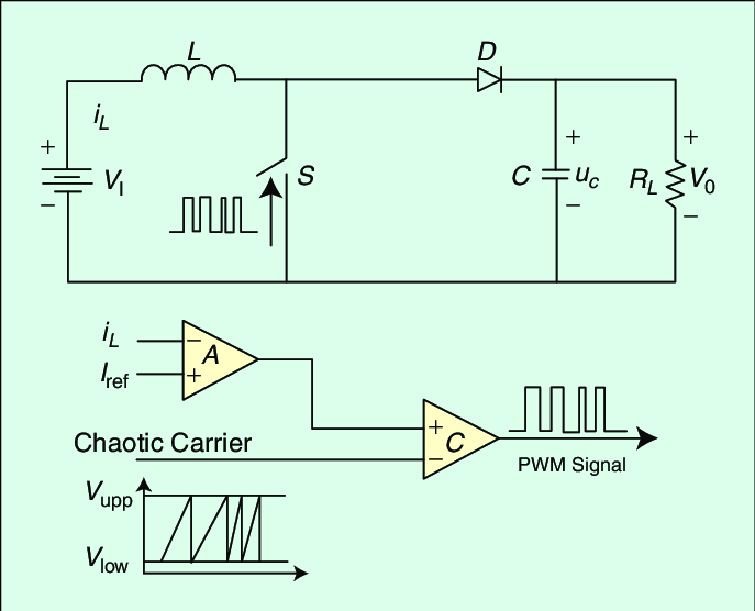
. The PWM pulses are obtained by comparing an input stream with a triangular wave. In our examples we set the frequency ft of the triangular wave at 15 KHz. The PWM signal is used to drive the power switches controlling the current flowing into the load. Electro-magnetic interference is produced due to several factors, related to the existence of rapidly varying high-level voltages and currents. More precisely, as far as the involved currents are concerned, ispk (t) is never perfectly filtered hence there is always a high frequency component in the current flowing through the wires connecting the power bridge The proposed switch frequency modulated PWM can be schematized as in figure
FIG2.FREQUENCY MODULATED CHAOTIC SWITCHING CONVERTER
4. CONDUCTED EMI CALCULATION
SPWM switching strategies under various circuit conditions (Mf, Ma and input dc voltage) are simulated to get basic knowledge of noise magnitude. Simulation is performed at the circuit level in the time-domain using the ORCAD software package to generate a set of waveforms covering full cycle time. Fig. I shows the simulation circuit, which consists of a line impedance stabilization network (LISN), diode rectifier, dc link filter and bridge rectifire. There are two purposes of the LISN The first is to prevent noise from the ac power mains from contaminating the measurement, and the second is to present a (relatively) constant impedance (50Q) to the product instead of the variable impedance one sees looking back into the power mains. LISN specifications are R,=5.52ohm; R2=50ohm; L1=L2=luH and C1=C2=0.lluF. The noise is measured across the LISN resistors R2 and the FFT gives the conducted emission of the noise voltage.
FIG3.IMPLEMENTATION OF TRAINGULER
FIG4. INPLEMENTATION OF PWM
FIG5.TRIANGLE AND SIN AND -SIN
FIG6.PULSE FOR RECTIFIRE SWITCHES
FIG7.RECTIFIRE CIRCUIT WITH (LISN) NETWORK
FIG8.RECTIFIRE OUTPUT
FIG9.CONDUCTED EMISSION OF NOISEVOLTAGE
BY FFT
5. A CHAOTIC OSCILLATOR
Chaos phenomenon has been studied extensively in various areas of science such as biology, ecology, physics, and optics. Among the already known chaotic oscillators, Chua’s circuit is endowed with virtually every bifurcation phenomena because it is the only chaotic system which can be easily built, simulated, and tractable mathematically. Its supreme simplicity and robustness has made it the circuit of choice for practical applications including: secure communications, visual sensing, neural networks, dry turbulence, nonlinear waves and music. Furthermore, in electronics Chua’s circuit is a very interesting and simplest autonomous circuit which exhibits bifurcation and chaotic phenomena, and it can be implemented by five circuit elements: one inductor, two capacitors, one linear resistor (R), and one nonlinear resistor ( R N ) which is well-known as Chua’s diode
FIG10.BASIC CHUA’S CIRCUIT
6. WORKING PRINCIPLE
The working principal of chaotic frequency modulation technique is same as simple frequency modulation technique, here PWM frequency spread chaotically poses a continuous spectrum and energy can be distributed having lower amplitude Then the EMI will be suppressed effectively
FIG11.SPECTRUM OF A FREQUENCY MODULATED SIN SIGNAL
7. CIRCUITRY AND PSPICE SIMULATION
A PSpice simulation of a double scroll attractor is shown in Fig. 1(b) with L = 180 _H, C2 = 1 nF, R = 1:6 K, C1 = 100 pF, R1 = R2 = 22K, R3 = 3:3 K, R4 = 2:2 K and using the commercial AD844 CFOA biased with ±9 V. The same values of R; R1; R2; R3; and R4 as in [8] are used. However, the inductor and capacitors are scaled down to extend the operating frequency, making use of the excellent performance of the CFOA at high frequencies. Instead of wasting the current output (I) of the first CFOA, we investigated the effect on the chaotic behavior of using it to drive a load resistor. It was found that the smaller the load (higher driving capability) the smaller the value of R3 required to maintain chaos. The output current (I) and voltage (VO) are shown in Fig. 2 with a 5-k load and with R3 = 500ohm…
FIG12. PSPICE MODEL OF CHAOTIC OSCILLATOR
FIG13 .CHAOTIC O/P WAVEFORM
FIG14.RECTIFIRE O/P USING CHAOTIC CIRCUIT
FIG15.CONDUCTED EMISSION OF NOISE VOLTAGEBY FFT USING CHAOTIC CIRCUIT
8. CONCLUSIONS
PWM drive pulse is the original source of switch
Converter EMI. Based on the analysis of the constant frequency scheme, the periodical frequency spreading scheme and the chaotic frequency-spreading scheme, this paper has discussed the mechanics and characters of the chaotic PWM suppressing EMI in converter. Simulations have been made on an AC-DC converter. The experiment results show that the EMI spectrum is completely decided by the PWM drive pulse. And after chaotic frequency-spreading, the converter it is clearly shown by the fft spectrum conducted emi is reduced after using chaotic circuit. Effectively, the envelopes of the power spectra of the conducted EMI can in principle be reduced. So the switch converter with chaotic frequency-spreading may become the next generation converter in the near future
9. REFERENCES
1.Ru Yang, Bo Zhang( IEEE Member), Liande Yu, Zuolian Liu “Quantification of Chaotic Spectrum and EMI Suppression in Converters” IEEE 2008.
2. R. Yang, B.Zhang, F.LI and J.J Jiang “Experimental research of chaotic PWM suppressing EMI in converter” IEEE2006
3. A.Santolaria, J.Balcells, D.Gonzalez, “Evaluation of switching frequency modulation in EMI emission reduction applied to power converters”, IEEE circuit and system, pp. 2306-2311, 2003.
4. Josep Balcells, Member, Alfonso Santolaria, Antonio Orlandi, Senior Member, David Gonzalez, Member, and Javier Gago “EMI Reduction in Switched Power Converters Using Frequency Modulation Techniques ”,IEEE 2005. ].
5. Zheng Wang , K. T. Chau, and Chunhua Liu “Improvement of Electromagnetic Compatibility of Motor Drives Using Chaotic PWM” IEEE 2007.
6. Tetsuro Tanaka, Tamotsu Ninomiya and Koosuke Harada “Random-switching control in DC-TO-DC converters” IEEE-1989.
7. M. Kuisma “Variable Frequency Switching in Power Supply” IEEE AES system magazine 8 September 2003.
.