K. B. SinghDepartment of Physics,
Govt. Polytechnic college, Darbhanga
E-mail:kbsphysics@yahoo.co.in
ABSTRACT
In this paper, characteristic impedance, Phase velocity, Attenuation constant and Selectivity, which are important parameters to be discussed. The metallic and dielectric loss has been also calculated for the study of selectivity of microstriplines with fused quartz as substrate and its variation with strip width and operating frequency-using computer added technique. The calculation of selectivity of the microstripline structure keeping strip width and permittivity fixed has been carried out for different frequencies. In the growing edge of computer and information technology the communication system has shrinked to a miniaturized size, lightweight and less expansive. It is due to advent of microwave integrated circuit, which gave birth to planar microwave transmission structure. Microstripline structure appears to be the most convenient and easy to fabricate. This furnishes very useful information for designing microstrip line coupler and resonators of high selectivity. KEYWORDS: Microstripline, Attenuation factor, Selectivity
1. INTRODUCTION
The increasing importance of miniature planar microwave integrated circuits has renewed interest on the part of microwave circuit’s designers in the various form of planar strip transmission line such as stripline, microstripline, slotline, coplanar stripline and coplanar waveguide etc. Out of these microstriplines appears to be most simple, convenient, inexpensive and easy to fabricate. Due to openness of the structure radiation, conductor and dielectric losses need to be minimized to insure the field to be confined near the metal strip. Use of dielectric substrate of suitable permittivity and low loss tangent is necessary. Also electromagnetic field lines extend in the space above the strip, the microstrip structure becomes a mixed dielectric transmission line. This needs effective permittivity to be taken into account. The microstripline consists of a narrow “strip” conductor of width (W)and thickness(t) separated from a conducting ground plane by an intervening supporting dielectric substrate of thickness and width much greater than the strip width. For maximum circuit size reduction, the dielectric constant of substrates now being used is of the order of two or higher. But due to smaller loss tangent or low |
|
dissipation factor fused quartz like substrate is preferably used. For design purpose it is necessary to study the characteristic parameters of the stripline and different losses occurred in this structure during the propagation of electromagnetic waves through the structure. The TEM-mode of the propagation is considered in the lower giga hertz range of frequency. This study provides and easy method for the calculation of the selectivity of the microstriplines using different width of the conductor strip. As the study of selectivity of microstriplines has not received much attention in recent years. This restricts our attention to the study of variation of selectivity with strip width and operating frequency. This will furnish useful information for design of the microstriplines of given characteristic impedance operative at given frequency, microstriplines couplers and resonators of high selectivity.
2. BRIEFS OF MICROSTRIPLINE
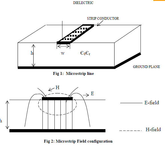
This was realized with a planar form of single wire transmission line over a ground plane, called microstrip[1].Microstrip employs a flat strip conductor suspended above a ground plane by a lowloss dielectric material. The size of the circuit can be reduced through judicious use of a dielectric constant some 2-10 times that of free space (or air), with a penalty that the existence of two different dielectric constants (below and above strip) makes the circuit difficult to analyze in closed form (and also introduces a variability of propagation velocity with frequency that can be a limitation on some applications).Microstripline is an inhomogeneous structure. It consists of a narrow conductor strip one side of it a dielectric substrate and the other side being completely metalized to serve as a ground plane as shown in Fig-(1). Though the structure is open and suffers from radiation, metallic and dielectric losses, fused quartz substrate with copper conductor is used to minimize the losses. The microwave energy propagates both in the dielectric substrate below the metal strip and in the air region above. Fraction of power flows outside the substrate depending on the width of the metal strip. So, effective dielectric constant is considered instead of considering relative dielectric constant. The field configuration distribution is shown in fig-2. In the lower giga, hertz range of frequency TEM-mode of propagation of microwave is considered as proposed by H.A.Wheelar [2, 3]. |
3. CHARACTERISTIC IMPEDANCE
For the study of selectivity of microstriplines it is necessary to study the characteristic impedance and its dependence on the geometry of the microstriplines using Wheelar’s conformal transformation technique which converts the microstrip geometry into parallel plate geometry [4, 5]. The knowledge of capacitance provides the knowledge of characteristic impedance of the microstrip geometry using formula
Z0 = 1/VpC (1) Where Vp = Phase velocity of the microwave passing through the microstrip geometry and C = Capacitance per unit length of the microstrip structure. Considering the geometry of the (fig-1); Capacitance per unit length of the structure is given as:

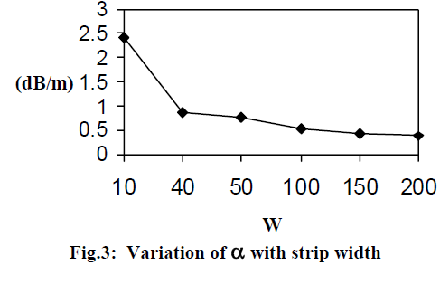
a = ac + ad (4) Where, ac denotes metallic loss and ad denotes dielectric loss factor. 4.2 METALLIC LOSS Pucel et al [6] derived the expression for ac as; ac = 8.68 (RS / Z0w) dB/unit length (5) Where, RS = Surface resistivity = v(pµf / sc) O/m s2 = 11.58 x 10⁻³ O/m2 f = operating frequency = 2 GHz ac = 1.7 µO for Cu. µ = 15.57 x 10⁻⁷ H /m for Cu Putting different values of w and Z0, ac has been calculated. 4.3DIELECTRIC LOSS Welch and Pratt [7] have established an expression for dielectric loss, further used by Pucel et al which is expressed as; ad=(27.3tand/?0)(?r/v?re)(?re -1/?r-1) dB/unit length (6) Where, ? 0 = Free space wavelength = 15 cm at 2 GHz frequency. ?r = 3.75 Tan d= 10-4 for fused quartz ?re = Effective dielectric constant of the medium used. = (?re+1)/2 for narrow strip. Calculating these losses selectivity can be studied. A simple formua for the selectivity of the microstrip line has been given by Delinger [8] and Schneider [9] and expressed as; Selectivity = S = 27.3 /a ?g (7) Where, ?g = guide wave length of microstrip line. This shows that selectivity of microstrip line is the inverse of total loss factor and guide wave length. With the help of equation (4) total loss factor has been calculated and using equation (7) selectivity has been obtained. Further exhaustive computations have been carried out for obtaining selectivity for different strip width and different frequency. The variation of total loss factor with strip geometry is shown in Fig-
smaller in lower GHz frequency range than the higher GHz range of frequency. For higher selectivity or figure of merit and higher storing ability higher frequency, higher relative permittivity and wider metal strip are more useful. This study helps a designer to design and fabricate a practical microstrip transmission structure, which will be used in coupler, filter, and oscillator and antenna circuits. This work has the scope for future work also.
Acknowledgement
The authors wish to thank Dr. H.L.Sah, Ex. H.O.D. Deptt. of Electronics, B.R.A.Bihar University, Muzaffarpur and Dr. S.K.Kaul, I.I.T. Delhi, for the guidance and inspiration.
References:
[1] Vendelin, G., Pavio, A., and Rohde, U., " Microwave circuit Design using Linear and Nonlinear Technique, j. Wiley, 1990. pg. 37-44. [2] H.A. Wheeler, “Transmission line properties of parallel strip separated by dielectric sheet”, IEEE, Tr. MTT-13, pp 172-185, 1965. |
|
?re = Effective dielectric constant of the medium = (?r +1)/2 for narrow strip. Based on equation-3, a computer program has been developed and exhaustive computations have been carried out for calculations of characteristic impedance and its variation with width of metal strip in the lower giga hertz range of frequency. The result shows that for wider strip field concentration is larger below it causing larger flow of electromagnetic energy. As a result, characteristic impedance of the microstrip structure becomes smaller. But reverse is the case with narrow metal strip. This provides an useful information for the design of the microstrip structure of good selectivity. 4. CALCULATION OF LOSSES
4.1SELECTIVITY
The selectivity or figure of merit of microstriplines is very significant characteristic need to be studied for the design of microstrip structure and its usefulness in couplers, circulators, resonators, antenna and coupled cavities of high selectivity. The selectivity depends on the losses taking place inside the structure during the flow of microwave energy. There are too important losses in this structure:
(i) Metallic loss
(ii) Dielectric loss Assuming these losses per unit length to be small, the term attenuation factor a is used to represent this loss. Here a is written as:
The selectivity has been plotted against strip width and operating frequency is shows in Fig-(4) & (5).
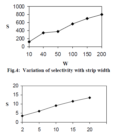
Fig-5: Variation of selectivity with operating frequency
5. RESULT & DISCUSSION
Variation of total loss factor with width of metal strip reveals that with increase of width total loss decreases sharply showing concentration of more and more energy below the strip in the dielectric medium. Also, guide wavelength shows a slight decrease with increase of width of metal strip. Further variation of selectivity of microstrip line shows a sharp increase in selectivity with increase of metal strip width. The calculations of selectivity of the structure keeping strip width and permittivity fixed have been carried out for different frequencies. The result has been plotted keeping frequency on X-axis and selectivity on Y-axis shown in Fig-(5). This shows that selectivity increases with increase of frequency. The rate of increase is almost the same in the lower GHz frequency range but becomes abnormal high in higher GHz frequency range of frequency dispersion effect is higher. Thus, selectivity is smaller for narrow strip and larger for wide strip. The selectivity of microstrip line using Copper strip and fused quartz dielectric substrate has been experimentally obtained by J.H.C.Van et al [10] which shows good agreement with the present results.
6. CONCLUSION
This concludes that wider metal strip is more useful for larger flow of power through the structure with smaller dissipation. But dispersion effect is [3] P. Selvester, “TEM wave properties of microstrip transmission lines and of coupled pair of microstrip lines”, IEEE Trans. Microwave Theory Technique, vol.16, pp.1021-1027, 1968.
[4] K.B.Singh & H. L. Sah, “Investigation of Characteristics of Microstrip directional coupler”, J. of Institute of Engineers, India vol.80, pp.36-42, March 2000.
[5] S.K.Kaul, “Strip line transmission for MIC’s”, Wiley Publication, New Delhi, 1992.
[6] R.A. Pucel et al, “Losses in Microstrip”, IEEE MTT, vol. 16, pp. 342-350, 1968.
[7] J. D. Welch and H. J. Pratt, “Losses in Microstrip Transmission System for MIC”, NEREM, Ree, vol.8, pp. 100-101, 1966.
[8] E. J. Denlinger, “A frequency Dependent Solution for Microstrip Transmission Lines”, IEEE Tran. MTT, Vol. 19, pp. 30-39, 1971.
[9] M.V. Schneider, “Dielectric loss in integrated Microwave circuits”, Bell system, Technical Journal, vol.48, pp. 2325-2332, 1969.
[10] J.H.C.Van et al, “Properties of microstriplines on fused quartz”, IEEE- Tr. MTT, pp. 113-115, Sep. 1970.
|
|