Abstract
Solid rocket propellants are used in propulsion systems of rockets, missiles and launch vehicles because of their simplicity, ease of operation and less deployment time. Although propellants are supposed to burn and provide propulsive force to make various payloads airborne and propel them towards targets, they are also supposed to possess sufficient mechanical strength to counter a gamut of experienced loading conditions. Right from manufacture to transportation to storage to applications, they are continuously stressed by environmental changes (temperature and relative humidity), jolt, bump, self-weight, acceleration and internal pressure loading conditions. In nutshell, solid propellants, which are designed to give energy by combustion are supposed to have high mechanical strength to withstand various loads and retain their predefined shape till successful operation.
Current trend in propellant technology revolves around developing case-bonded solid propellant rocket motors for various applications for higher volumetric loading and increased range/payload requirements. Casebonding stresses solid propellant a bit more. The mechanical properties of propellants, favourable for such case-bonding applications are high percentage elongation, moderate tensile strength and sufficient initial modulus.
Since current propellants are similar to highly filled (85-88%) polymers, their mechanical properties are combination of polymeric/elastomeric mechanical properties and particulate-matter mechanical properties. Additionally, propellant mechanical properties vary with temperature as well as strain rate. This leads to a highly complex behavior shown by solid rocket propellants.
This article gives a brief account of conventional approach for mechanical characterization of solid propellants. The effect of strain rate on initial modulus of propellants is explained and a correlation is obtained by regression analysis to predict initial modulus of solid propellant at different strain rate without actually testing them under all situations. A concept of uniform final modulus independent of strain rate is also introduced.
|
|
Introduction
All modern rockets, missiles and launch vehicles use solid propellants, based on casting technology. Main ingredients of solid propellants are polymer based binder (16%), solid oxidizer powder (68-85%) and metallic fuel powder (0-17%). Since both particulate and polymers are characterized by different types of mechanical properties, combined contribution of each ingredient is expected from solid propellants. Since stress-free temperature during propellant processing is higher than normal room temperature, solidified propellants are always under thermal stress during subsequent storage and transportation. After solid propellants are obtained, they are transported, where jolt, bump and vibrations are obvious loading environment. During storage, change in temperature and relative humidity of atmosphere, stresses propellants further. During rocket operation, hot combustion gases create high pressure inside rocket motor chamber, which loads unburnt part of solid propellants. Launch and Flight acceleration, sharp maneuverability in flight and air-thermo-chemical heating are some additional loads, experience by propellants during operation.
These all loads are considered during design of a solid propellant configuration. All solid propellant fulfill ballistic requirements to traverse a pre-defined trajectory, velocity and acceleration. Additionally, propellants must have sufficient strength to show structural integrity till successful completion of operation. Any design of solid propellant must have to satisfy ballistic requirements, processing requirements and mechanical properties requirements. Although ballistic and processing requirements are parts of system requirements, tailoring of mechanical properties remains in the purview of propellant manufacturers and structurally safe propellant for satisfying mission specifications is a major concern in modern era.
Background of Mechanical Characterization
Characterization of solid propellant as load bearing member has been stressed in several reports and papers. Importance of proper constitutive equations to predict mechanical properties of solid propellants are |
discussed in NASA report1 and effect of propellant compressibility, dependence of time and temperature are also established. Theoretical stress analysis and failure property generation are also discussed in this report. In yet another report from AGARD2 (Advisory Group for Aerospace Research and Development), Finite element analysis is conducted for solid rocket propellants, shaped in various forms. Mechanical characterizations, elaborated in this report, are stressrelaxation test, uni-axial tensile test (STANAG 4506), poisson’s ratio and bulk modulus determination. Similarly structural service life of propellant3 and effect of environmental conditions on cumulative damage4 are also point of discussion in papers.
Leaving these advanced techniques aside, in early 60s, propellants are characterized as viscoelastic material, behaving as rubberlike filled elastomers5-6. Time – dependent tensile properties, quasi-equilibrium modulus, Temperature dependence of mechanical properties are also illustrated. These generated properties are used for assessing structural margin of safety for actual systems7-9. Currently, several constitutive models are proposed by different scholars to express constitutive equations of propellant mechanical properties10-11.
Experimental results
The uni-axial tensile testing of solid propellant sample in flat dog bone shape (critical cross-section area : 3.97mm x 6.07mm = 0.241 cm2) as per ASTM specification is carried out in constant rate of loading universal testing machine. The strain rate is 50mm/min and gauge length is 45mm. A sample curve is shown in figure 1.
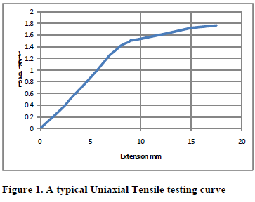
Figure 1. A typical Uniaxial Tensile testing curve
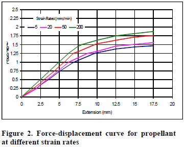
initial modulus and one final modulus, later being much lower than initial modulus. When propellant samples are tested at different strain rates, it is clear from figure 2 that initial modulus varies but final modulus remains same for each strain rate. Although forces are different in later part for different strain rate curves, the slope or modulus value remains unaffected. The initial modulus varies with strain rate and higher strain rate gives higher modulus. This is because propellant cannot respond as fast as movement of grips in high strain rate situation and particulate behavior dominates over polymeric behavior. To simulate the change in initial modulus values, rotating loadextension curve by certain angle can be one alternative. With suitable selection of rotation angle, initial modulus can be made equal at different strain rates. The force-extension curves, rotated by suitable angle so as to match initial modulus at 50mm/min strain rate, are given in figure 3. Rotation angles for 5mm/min, 20 mm/min, 50 mm/min and 200 mm/min are 1.5o, 0.9o, 0o and -1.6o respectively. Similarly, all curves can be rotated to match any of the given strain rate curve. If 5 mm/min strain rate curve is referred then all the curves are to be rotated in clockwise direction (negative) and rotation angles are linearly varying and have values 0o, -0.6o, -1.5o and -3.1o for 5mm/min, 20 mm/min, 50 mm/min and 200 mm/min strain rates respectively. 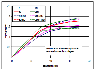
Figure 3. Force-displacement rotated curves for different strain rates
Similarly for equality of final modulus a linear translation in vertical direction may give superposed curve for different strain rates. The displaced curves with reference as 50mm/min strain rate curve are Jrl of Spacecraft, Vol 19, No 6, 1981, P564-570, AIAA-81-1544R.
iv. “Environmental Effects on Cumulative Damage in rocket Motors”, R.AS. Heller, M.P. Singh and H. Zibdeh, Jrl of Spacecraft, Vol 22, NO 2, Mar-Apr 1985, P149-155.
v. “Viscoelastic Properties of rubberlike Composite Propellants and Filled Elastomers”, Robert F. Landel and Thor L. Smith, ARS journal, May 1961, P599-608. vi. “Recent Advances in Mechanical Properties
evaluation of Solid Propellants”, James H. Wiegand, ARS journal, June 1962, P521-527.
vii. “Stresses and Strains in Solid Propellants During Storage”, George Lianis, ARS journal, May 1962, P 688-692
|
|
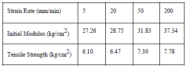
For this curve, value of initial modulus of propellant is calculated to be 32.76 kg/cm2 (1 kgf x 45mm/(0.241cm2 x 5.7mm)). The curve is plotted upto maximum load or stress-level. Peak load is 1.76 kgf and extension corresponding to peak load is 17.5 kgf. From this, tensile strength is calculated to be 7.3 kg/cm2 and percentage elongation is 38.88% (17.5/45). The propellant samples from same lot are tested at different strain rates like 5 mm/min, 20 mm/min and 200 mm/min. The values of tensile strength and initial modulus are represented in table 1. It is clear that as strain rate increases, both initial modulus and tensile strength increases. Percentage elongation at highest value of tensile stress is almost invariant with strain rate. A superposed curve of load extension is shown In figure 2. Table 1. Variation of Mechanical Properties with Strain Rate
Analysis and Discussion
It is clear from figure 1, that propellant samples show linearity upto around one-third of their extension till peak stress. It is also clear that polymeric binder is responsible for non-linearity in the behavior. Additionally, binders are polymeric masses, which show visco-elasticity or time-dependent or strain-ratedependent behavior. Clearly propellant can be characterized as having two modulus values – one
shown in figure 4. Vertical linear displacements for 5mm/min, 20 mm/min, 50 mm/min and 200 mm/min are 0.265kgf, 0.19kgf, 0kgf and -0.129kgf respectively. Similarly any of the strain rate curves can be taken as base and linear translation in vertical direction can simulate final modulus for other strain rates. For example, if 200mm/min strain rate curve is considered as base or reference, then translation needed for equality of final modulus are 0.394kgf, 0.319kgf, 0.129kgf and 0kgf for 5mm/min, 20 mm/min, 50 mm/min and 200 mm/min strain rates respectively. With translation and rotation applied suitably, to curve generated at single strain rate, force-extension curves at all strain rates can be generated. 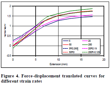
Conclusion
From analysis it can be concluded that polymer behaves as linear elastic material till only one third part of maximum extension or strain. The initial modulus values are much higher than final modulus value. As strain rate increases, initial modulus and tensile strength of propellant increase. However final modulus value remains invariant for strain rate. A mathematical correlation for simulating initial modulus by rotation of and final modulus by linear translation of loadextension curve is also proposed in the article. This helps in reducing number of experiments for complete characterization of solid propellants for mechanical properties assessment.
Reference
i. “Solid Propellant Grain Structural Integrity Analysis”, NASA SP-8073, June 1973.
ii. “Structural Assessment of Solid Propellant Grains”, AGARD-AR-350, Dec 1997.
iii. “Structural Service Life Estimation for a Reduced Smoke Rocket Motor”, D.I. Thrasher and J.H. Hildreth,
viii. “Stress-Strain Equations for Case-Bonded Solid Propellant Grains”, Charles H. Parr, ARS Journal, Aug 1960, P778-779.
ix. “Stresses owing to Internal Pressure in Solid Propellant Rocket Grains”, Howard B. Wilson, ARS journal, Mar 1961, P309-317.
Principle Applied for Predicting Mechanical Properties of Solid rocket Propellants”, Radun Jeremic, Propellant, Explosives, Pyrotechnics, Vol 24, 1999, P221-223
“High Strain-Rate Constitutive Models for solid Rocket Propellants”, Sook-Ying Ho, Jrl of Propulsion and Power, Vol 18, No 5, Sep-Oct 2002, P 1106-1111.
|
|